DC motor Characteristic Curvers
11 Apr 2015DC Motor Equilibrium Analysis
In this article we will look DC motor characteric curves and see how we can obtain parameters to model the DC motor from commonly provided specifications in motor Datasheet.
Equilibrium analysis
In the article “DC motor First order approximation” we saw how to characterize a DC motor using basic parameters provided in the motor Datasheet and predict the speed and responsiveness of motor for any given input voltage.
Let us look at some of parameters in mode detail under steady state conditions with a load.We apply a voltage and wait till the motor achieves constant velocity .
If we apply a voltage source to the motor terminal and mechanical load torque $\tau$ on the rotor
$ b \dot{\theta} = K_{t} i -\tau $
$ Ri = V - K_{b}\dot{\theta}$
Solving we get
$ i = \frac{b \dot{\theta} + \tau}{K_t}$
$ V= R \frac{b \dot{\theta} + \tau}{K_t} +K_{b}\dot{\theta}$
$ \dot{\theta} \big(\frac{Rb}{K_{t}}+K_{b}\big) = V - \frac{R*\tau}{K_{t}} $
$ \dot{\theta} \big(b+\frac{K_{b}K_{t}}{R}\big) = \frac{VK_{t}}{R} - \tau $
\[\tau =\frac{VK_{t}}{R} -\dot{\theta} \big(b+\frac{K_{b}K_{t}}{R}\big)\] \[\dot{\theta} = (\frac{VK_{t}}{R} - \tau ){\big(b+\frac{K_{b}K_{t}}{R}\big)}^{-1}\]- Slope of torque speed graph indicates inverse proportionality due to negative sign.
- The linear relationship between the torque provided by a motor and the speed at which it operates is specific to the input voltage at the motor’s leads
Thus we can plot the load v/s speed graph at specified voltage and power specifications.
Let us plot the torque v/s speed graph for nominal voltage of 12V and let load torque vary from 0 to 50 mNm and observe the RPM and power requirement of the motor.
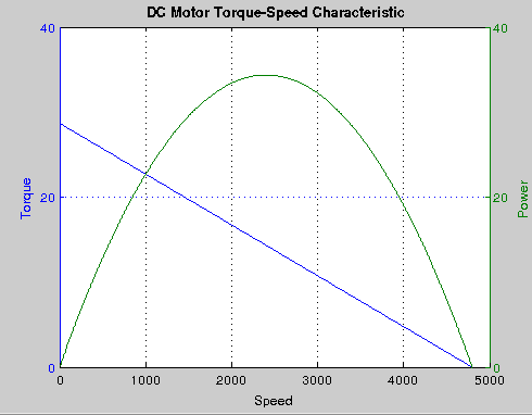
- At zero torque, the speed is highest. This speed is called no-load speed $\dot{\theta}_{n}$. The no-load speed can easily be calculated from the applied voltage and the speed constant of the motor.
- Enhancing the load torque leads to a linear reduction of the speed.
- Increasing the torque further reduces speed up to the point where the motor stops. The corresponding torque is called stall torque $\tau_{s}$
- The current corresponding to the stall torque is named starting current or no load current $i_{o}$
- A higher voltage results in a higher no-load speed
- The speed-torque gradient is unaffected with increase in voltage. Changing the applied voltage results in a parallel shift of the speed-torque line
- A strong motor is characterized by a flat speed-torque line. The speed drops only slightly when the load torque is enhanced. The value of the gradient is small.
- On a weaker motor the speed drop is larger. The speed-torque line is steeper and the value of its gradient is high.
Stall Torque
The torque provided by the motor when the rotor no longer turns is known as the stall torque.The torque of motor at zero speed.
It can be calculated as
$\tau_{s} =\frac{VK_{t}}{R} $
No Load Speed
The speed at which the rotor turns when no torque is provided is known as the no-load speed. The no-load speed is called as such since it is the speed at which the rotor will turn when there is no load connected.
\[\dot{\theta} = (\frac{V*K_{t}}{R}){\big(b+\frac{K_{b}K_{t}}{R}\big)}^{-1}\]No load speed is maximum speed that can be attained by the motor at the specified voltage .
Stall Current
The stall current is the current drawn by the motor when rotor no longer turns. The current draw is proportional to the torque.The stall current is the maximum current drawn by the motor under equilibrium condition.
$ i = \frac{\tau}{K_t}$ $ i = \frac{V}{R}$
No load Current
$ i = \frac{b\dot{\theta}}{K_{t}}$
Equilibrium Torque,Speed & Current
For a fixed voltage the equilibrium torque,speed and current can be expressed as
\(\tau =\tau_{s} -\dot{\theta} \big(b+\frac{K_{b}K_{t}}{R}\big)\) \(\dot{\theta} = \theta_{n} - \tau {\big(b+\frac{K_{b}K_{t}}{R}\big)}^{-1}\) \(I = I_{S} - \dot{\theta} \big(\frac{K_{b}}{R}\big)\)
Motor Datasheet
Not all motor manufactures provide parameters that can be used directly to model the motor.
The parameter like L,R,torque constant,backemf constant etc are called as Intrinsic Parameters of the motor.
The values like stall torque,stall current,no load speed and current are the values measured values and most often found in datasheets.
For example the important specifications of motor are often given in the form
- Nominal voltage 4.5V
- No load speed 23000rpm
- no load current 70mA
- Stall torque of 0.34mNm
Let us assume that we have also some intrinsic parameters like R
We know that the stall torque $\tau_{s} =\frac{VK_{t}}{R} $
Thus we can compute $K_{t}$ from the equation The no load speed is given by
\[\dot{\theta_{n}} = (\frac{VK_{t}}{R} ){\big(b+\frac{K_{b}K_{t}}{R}\big)}^{-1}\] \[\frac{\tau_{s}}{\dot{\theta_{n}}} =\big(b+\frac{K_{b}K_{t}}{R}\big)\]viscous friction coefficient $b$ can be computed from this equation.
Just by observing the graph we can determine the slope and the intercept ie $\big(b+\frac{K_{b}K_{t}}{R}\big)$ and $\frac{VK_{t}}{R}$.
Thus knowing the nominal voltage and estimate of R we can determine $K_{t}$ and $b$ from the graph itself.
Thus we have all the information we need for the first order model of a DC Motor.
For example for the portscape 216E motor http://www.portescap.com/sites/default/files/26n58_specifications.pdf we found that simple armature resistance yeilded a value of 15.2 and based on that given specifications ans above formulat the intrinsic model parameters computed are
Kt =0.0236
b =9.9544e-07
These are approximately equal to the values in the datasheet.
Mechanical Power
The mechanical power $P$ delivered by the motor is
$P = \tau \dot{\theta}$ $P =\tau_{s}\dot{\theta} -\dot{\theta}^2 \big(b+\frac{K_{b}K_{t}}{R}\big) $
We can find the velocity that provides the maximum power by computing the gradient wrt $\dot{\theta}$
$\dot{\theta_{max}} = 0.5\tau_{s}\big(b+\frac{K_{b}K_{t}}{R}\big)^{-1}$
$\dot{\theta_{max}} = 0.5\dot{\theta_{n}}$
Thus maximum mechanical power is achieved when motor is running at half the no load velocity.
At this point the torque is $\tau_{max} = 0.5\tau_{s}$
Thus maximum power is achieved when the torque is half of stall torque.
Since the current draw is proportional to the torque, then the current at the point of maximum power transfer shall also be one half of the stall current.
$I_{max} = 0.5I_{s}$
The maximum mechanical power produced by the motor is as follows $P_{max}=\frac{1}{4} \tau_{s}\dot{\theta}_{n}$
Thus maximum efficiency is obtained when speed is half no load speed and torque is half stall torque.
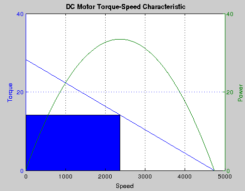
Power delivered by the motor is area of a rectangle under the torque/speed curve with one corner at the origin and another corner at a point on the curve
We can see the maximum area is obtained when
$\dot{\theta_{max}} = 0.5\dot{\theta_{n}}$
and
$\tau_{max} = 0.5\tau_{s}$
corresponding to the peak in the power v/s speed curve
Motor Efficiency
The efficiency $\eta$ of a motor is defined as the ratio between the input electrical power and output mechanical power
$\eta = \frac{P}{VI}$
$I = \frac{V_{S}}{R} - \dot{\theta} \big(\frac{K_{b}}{R}\big)$ $P_{i} = VI = V\frac{V_{S}}{R} - V\dot{\theta} \big(\frac{K_{b}}{R}\big)$ $ \tau =\tau_{s} -\dot{\theta} \big(b+\frac{K_{b}K_{t}}{R}\big)$ $P_{o} = \frac{K_{t}V_{s}}{R}\dot{\theta} -\dot{\theta}^2 \big(b+\frac{K_{b}K_{t}}{R}\big)$
$\eta = \frac{\frac{K_{t}V_{s}}{R}\dot{\theta} -\dot{\theta}^2 \big(b+\frac{K_{b}K_{t}}{R}\big)}{V\frac{V_{S}}{R} - V\dot{\theta} \big(\frac{K_{b}}{R}\big)}$
$\dot{\theta}_{me} = \frac{bc - \sqrt{b^2c^2-abcd}}{bd}$
where
$a = \tau_{s}-Kt*i_{o},$
$b = b + \frac{K_{b}K_{t}}{R},$
$c= \frac{V*Vs}{R},$
$d = V\big(\frac{K_{b}}{R}\big),$
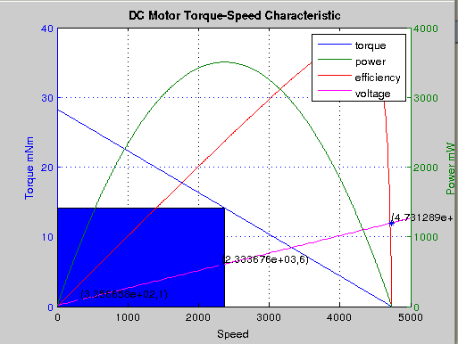
We can see from the plot that the velocity at max efficiency is 4237 rpm And operating of max power is different from that of max efficiency.
The first order model we enables us to plot the motor characteristics plot and observe the behavious of motor to a good degree of accuracy.
Code
The code to compute and plot the various DC motor curves can be found in file dcmotor2 at bitbucket repository https://bitbucket.org/snippets/pi19404/55ep
References
- http://www.portescap.com/sites/default/files/wp_drivers_for_ironless_dc_motors.pdf
- http://dsc.ijs.si/Damir.Vrancic/Files/dp7091.pdf -http://www.precisionmicrodrives.com/application-notes-technical-guides/application-bulletins/ab-025-using-spice-to-model-dc-motors
- http://www.ti.com/lit/an/slua076/slua076.pdf
- http://mechanical.poly.edu/faculty/slee/ME3411/Exp3.pdf
- http://mplab.ucsd.edu/tutorials/dc.pdf -http://ece.ut.ac.ir/Classpages/S89/ECE425/HW5SOL.pdf -http://www.site.uottawa.ca/~rhabash/ELG3311A4Ch9.pdf
- http://mplab.ucsd.edu/tutorials/
- http://www.cecs.uci.edu/publication/d-d-gajski-s-abdi-a-gerstlauer-and-g-schirner-embedded-system-design-modeling-synthesis-verification/
- http://www.ni.com/white-paper/4074/en/
- http://www.maxonmotor.com/medias/sys_master/8798985748510.pdf
- http://www.me.umn.edu/courses/me2011/arduino/technotes/dcmotors/
- http://lancet.mit.edu/motors/motors3.html
- http://www.delta-line.com/data/download/Brush_DC_Motor_Basics.pdf
- http://www.gearseds.com/files/Lesson3_Mathematical%20Models%20of%20Motors.pdf